john deere l120 wiring diagram pdf

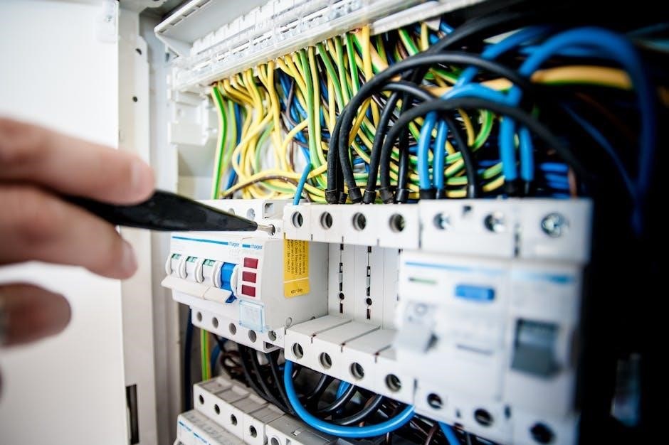
The John Deere L120 wiring diagram is a crucial resource for understanding and maintaining the tractor’s electrical system. Available in PDF format‚ it provides detailed schematics for diagnostics and repairs‚ ensuring safe and efficient troubleshooting for owners and technicians alike.
1.1 Overview of Wiring Diagrams
Wiring diagrams provide a visual representation of the electrical system‚ detailing connections‚ components‚ and circuits. They use symbols and color coding to simplify understanding. These diagrams are essential for diagnosing issues‚ planning repairs‚ and ensuring proper system functionality. For the John Deere L120‚ they cover everything from the ignition system to accessories‚ making them invaluable for both novice and experienced technicians.
1.2 Importance for Maintenance and Repairs
Wiring diagrams are essential for maintaining and repairing the John Deere L120. They help identify components‚ trace circuits‚ and diagnose electrical issues‚ ensuring accurate and efficient repairs. By guiding technicians through complex systems‚ these diagrams prevent errors‚ enhance safety‚ and prolong equipment lifespan‚ making them indispensable for both routine maintenance and troubleshooting electrical faults.

Key Components of the John Deere L120 Wiring Diagram
The diagram includes the battery‚ ignition switch‚ PTO clutch‚ solenoids‚ fuses‚ relays‚ and connectors. These components ensure proper electrical system function and safe operation of the tractor.
2.1 Electrical System Overview
The John Deere L120’s electrical system is designed for reliable operation‚ integrating components like the battery‚ ignition switch‚ and fuses. The wiring diagram provides a clear layout of connections‚ ensuring proper current flow and safe diagnostics. It simplifies troubleshooting by visually mapping circuits‚ solenoids‚ and connectors‚ making it easier to identify and resolve electrical issues efficiently.
2.2 Major Electrical Components
The John Deere L120’s electrical system includes key components such as the battery‚ ignition switch‚ fuses‚ PTO clutch‚ and solenoids. These elements work together to power essential functions like headlights‚ accessories‚ and the mower deck. Understanding their roles and connections‚ as detailed in the wiring diagram‚ is crucial for effective diagnostics and repairs‚ ensuring optimal tractor performance and safety.
2.3 Safety Precautions and Best Practices
When working with the John Deere L120 wiring diagram‚ always disconnect the battery to prevent electrical shocks. Use proper tools and ensure the tractor is on level ground. Avoid shortcuts or bypassing safety features. Wear protective gear like gloves and safety goggles. Refer to the manual for specific guidelines‚ and never attempt repairs without understanding the system fully to ensure safe and effective outcomes.

Types of Wiring Diagrams Available
The John Deere L120 wiring diagram PDF includes full system‚ PTO clutch‚ and accessories diagrams‚ providing comprehensive coverage for electrical troubleshooting and maintenance tasks.
3.1 Full System Wiring Diagram
The full system wiring diagram provides a comprehensive overview of the John Deere L120’s electrical circuits‚ including connections‚ components‚ and control modules. This detailed schematic is essential for diagnosing complex issues and planning repairs‚ offering a clear visual representation of the tractor’s entire electrical setup.
3.2 PTO Clutch Wiring Diagram
The PTO clutch wiring diagram focuses specifically on the electrical connections for the power take-off system. It details the circuits‚ relays‚ and sensors controlling the PTO clutch‚ enabling precise diagnostics and repairs. This diagram is essential for understanding and resolving issues related to the PTO engagement and disengagement functions on the John Deere L120 tractor.
3.4 Accessories Wiring Diagrams
Accessories wiring diagrams provide detailed electrical schematics for optional equipment like lights‚ snowblowers‚ or tillers. They guide the installation‚ troubleshooting‚ and maintenance of these add-ons‚ ensuring compatibility with the L120’s electrical system. These diagrams help owners and technicians connect accessories safely and efficiently‚ preventing potential electrical conflicts or system malfunctions.
How to Read and Interpret the Wiring Diagram
Understanding symbols‚ color codes‚ and circuit pathways is essential. Trace connections between components‚ identify power sources‚ and verify ground points to diagnose or repair electrical systems accurately.
4.1 Understanding Symbols and Notations
The John Deere L120 wiring diagram uses standardized symbols to represent components like switches‚ fuses‚ and connectors. Color-coded wires indicate power sources‚ ground connections‚ and signal paths. Familiarizing yourself with these symbols and notations is crucial for accurately tracing circuits and diagnosing issues. The PDF document often includes a legend or key to decode these elements‚ ensuring precise interpretations during repairs.
4.2 Navigating the PDF Document
The John Deere L120 wiring diagram PDF is structured with a table of contents‚ bookmarks‚ and a search function for easy navigation. Users can quickly locate specific sections‚ such as electrical systems or PTO clutch diagrams‚ by using keywords. The document often includes zoom and pan features‚ allowing detailed viewing of complex circuits. This ensures efficient access to the information needed for repairs or maintenance.
4.3 Cross-Referencing with Repair Manuals
For accurate repairs‚ the John Deere L120 wiring diagram should be cross-referenced with the repair manual. This integration ensures understanding of electrical systems and components. The manuals provide step-by-step instructions‚ while the wiring diagram offers visual schematics. Together‚ they help identify part numbers‚ locations‚ and connections‚ ensuring precise and safe repairs for optimal tractor performance and longevity.

Locating the John Deere L120 Wiring Diagram PDF
The John Deere L120 wiring diagram PDF can be sourced from official John Deere websites‚ third-party forums‚ or local dealerships. Ensure authenticity by verifying the source and cross-checking with repair manuals for accuracy.
5.1 Official John Deere Sources
Official John Deere sources provide authentic and detailed wiring diagrams for the L120 model. The John Deere website and authorized dealers offer downloadable PDFs‚ ensuring accuracy and reliability. These resources include comprehensive service manuals‚ parts catalogs‚ and specific wiring schematics for models like the L100‚ L110‚ L120‚ L130‚ and more. They are essential for safe and precise repairs.
5.2 Third-Party Websites and Forums
Third-party websites and forums provide accessible John Deere L120 wiring diagram PDFs. Platforms like forums and PDF repositories often host user-shared documents. For instance‚ a thread mentions a member offering the L120 wiring PDF via email. While convenient‚ verify the source’s authenticity to avoid inaccuracies. These communities can be invaluable for troubleshooting and repairs‚ offering diverse resources and support.
5.3 Local Dealerships and Service Centers
Local John Deere dealerships and service centers are reliable sources for obtaining the L120 wiring diagram PDF. These centers provide official‚ high-quality documents‚ ensuring authenticity and accuracy. Technicians at these locations can also offer expert guidance‚ making them a valuable resource for complex repairs. Visiting a dealership ensures access to genuine materials tailored to your specific tractor model.
Troubleshooting Common Electrical Issues
The John Deere L120 wiring diagram PDF is a key tool for diagnosing electrical problems‚ such as faulty fuses‚ sensors‚ or wiring connections‚ ensuring quick resolution.
6.1 Using the Wiring Diagram for Diagnosis
The John Deere L120 wiring diagram PDF is essential for diagnosing electrical issues‚ such as faulty fuses‚ sensors‚ or wiring connections. By referencing the diagram‚ users can identify the root cause of problems like malfunctioning PTO clutches or ignition systems. Start by locating the affected system‚ trace the circuit‚ and verify connections to pinpoint faults efficiently. Cross-referencing with repair manuals enhances accuracy.
6.2 Common Issues and Solutions
Common electrical issues with the John Deere L120 include faulty PTO clutch wiring‚ blown fuses‚ and damaged sensors. Solutions involve checking the wiring diagram for loose connections‚ verifying circuit integrity‚ and replacing defective components. Consulting the PDF ensures accurate repairs‚ while regular inspections prevent recurring problems. Addressing these issues promptly maintains tractor functionality and safety.
6.3 Tools and Equipment Needed
Essential tools include a multimeter for voltage checks‚ wiring testers for circuit verification‚ and a set of insulated screwdrivers for safe repairs. Diagnostic software and the wiring diagram PDF are crucial for identifying faults. Protective gear like gloves and safety glasses is recommended when working with electrical systems to ensure personal safety during troubleshooting and repairs.

The Role of the Repair Manual and Parts Diagram
The repair manual and parts diagram complement the wiring diagram by providing detailed instructions and part numbers‚ ensuring accurate repairs and maintenance for the John Deere L120.
7.1 Integration with Wiring Diagrams
The repair manual seamlessly integrates with the wiring diagram‚ offering step-by-step instructions for electrical system repairs. It provides part numbers and locations‚ ensuring accurate component identification and replacement. This integration is essential for diagnosing and resolving issues efficiently‚ avoiding mismatches and ensuring proper system functionality.
7.2 Detailed Instructions for Repairs
The repair manual offers comprehensive‚ step-by-step instructions for repairing the John Deere L120’s electrical and mechanical systems. It includes troubleshooting tips‚ part number identification‚ and tool requirements‚ ensuring precise and efficient repairs. This detailed guidance helps users address issues confidently‚ from wiring fixes to component replacements‚ using the wiring diagram as a reference;
7.3 Part Number Identification
The repair manual and parts diagram provide clear part number identification for the John Deere L120. This ensures accurate ordering of replacement components. Cross-referencing with the wiring diagram helps locate specific parts efficiently. Detailed listings in the PDF guide minimize errors‚ while tools like parts lookup features simplify the process of finding and verifying correct components for repairs and maintenance.

Safety Practices When Working with Electrical Systems
Always disconnect the battery and wear protective gear when working with electrical systems. Use the wiring diagram to identify live circuits and ensure safe diagnostics and repairs.
8.1 Essential Safety Gear
Always wear insulated gloves‚ safety goggles‚ and a non-contact voltage tester when working with electrical systems. Use the wiring diagram to identify live circuits and ensure safe diagnostics. Consult the John Deere L120 manual for specific safety guidelines to prevent accidents and ensure proper handling of electrical components.
8.2 Proper Tools and Documentation
Use insulated tools like pliers and screwdrivers to prevent electrical shocks. Keep a multimeter handy for voltage testing. Refer to the John Deere L120 wiring diagram PDF and repair manual for accurate diagnostics. Ensure all documentation is up-to-date and easily accessible to avoid errors during repairs or maintenance.
8.3 Emergency Procedures
In case of an electrical emergency‚ disconnect the power source immediately and consult the John Deere L120 wiring diagram PDF. Isolate the affected circuit to prevent further damage. Ensure the tractor is in a safe‚ cool environment. Avoid restarting until the issue is resolved. Always prioritize safety and refer to the repair manual for guidance if unsure.
Tips for Effective Use of the Wiring Diagram PDF
Use zoom and pan features for detailed circuit analysis. Bookmark frequently accessed sections and cross-reference with repair manuals for clarity. Keep the document organized for quick navigation.
9.1 Navigating and Searching the Document
Use the table of contents or thumbnails to quickly locate sections. Employ the search function to find specific components or circuits. Bookmark pages for easy access and cross-reference with repair manuals for comprehensive understanding. Zoom in on detailed diagrams for clearer visibility and pan across pages to track connections effectively.
9.2 Utilizing Zoom and Pan Features
Use the zoom feature to enlarge specific sections of the wiring diagram for detailed inspection. Pan across the document to navigate between pages seamlessly. This ensures clarity when tracing complex connections or identifying components. Zooming allows precise viewing of small details‚ while panning helps maintain context within the larger electrical system layout.
9.4 Keeping the Document Organized
Organize the PDF by bookmarking key pages for quick access. Save the document in a designated folder on your device for easy retrieval. Use digital tools to highlight and annotate important sections‚ ensuring the wiring diagram remains clutter-free and user-friendly for future reference and maintenance tasks.

Regular Maintenance Using the Wiring Diagram
The wiring diagram aids in scheduling and performing routine checks‚ ensuring all electrical components function optimally. It helps verify connections‚ test circuits‚ and identify worn parts‚ preventing potential issues and extending the tractor’s lifespan.
10.1 Preventive Maintenance Schedule
The John Deere L120 wiring diagram supports a preventive maintenance schedule by guiding routine inspections of electrical connections‚ switches‚ and fuses. It helps identify worn-out parts before they fail‚ ensuring reliability. Annual reviews of the wiring system‚ battery checks‚ and blade inspections are crucial for optimal performance and longevity.
10.2 Updating and Verifying the Diagram
Regularly updating and verifying the John Deere L120 wiring diagram ensures accuracy and compliance with any manufacturer updates. Users should cross-reference the PDF with official sources or repair manuals to confirm details. This step is essential for maintaining the tractor’s electrical integrity and preventing potential issues during repairs.
10.3 Record Keeping and Documentation
Maintaining detailed records of repairs‚ updates‚ and wiring diagram modifications is essential for long-term tractor maintenance. Save PDF copies of the wiring diagram and repair manuals‚ noting repair dates and parts replaced. Keep a log of diagnostic steps and outcomes for future reference. Organized documentation ensures compliance with safety standards and simplifies future troubleshooting.


Leave a Reply
You must be logged in to post a comment.